Interfacing Relay Module with Arduino
In this project, we will demonstrate how to interface a relay module with an Arduino board. A relay module is an electrical switch that allows low-power microcontrollers like Arduino to control high-power devices such as motors, lights, or appliances. We will control the relay module using Arduino and switch an external device on and off.
Hardware Required:
- Arduino board (e.g., Arduino Uno)
- Relay module
- External device (e.g., motor, light bulb, or fan)
- Jumper wires
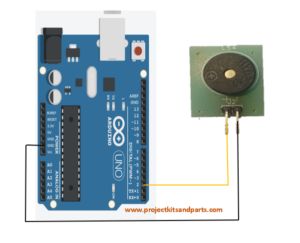
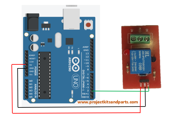
Circuit Diagram: Connect the components as follows:
Connections Table:
| Arduino Board | Relay module |
| 5v (vcc) => GND => PIN 2 => | Vcc GND RLY |
Below is the Arduino code to control the relay module:
// www.projectkitsandparts.com
// Define the pin connected to the relay module
const int relayPin = 2;
void setup() {
// Set the relay pin as an output
pinMode(relayPin, OUTPUT);
}
void loop() {
// Turn on the relay
digitalWrite(relayPin, HIGH);
// Wait for 2 seconds
delay(2000);
// Turn off the relay
digitalWrite(relayPin, LOW);
// Wait for 2 seconds
delay(2000);
}
Code Explanation:
- The relayPin variable is declared and set to the pin number connected to the relay module.
- In the setup() function, the relayPin is set as an output using the pinMode() function.
- The loop() function is where the relay control happens.
- The relay is turned on by setting the relayPin to HIGH using digitalWrite().
- The program waits for 2 seconds using delay(2000).
- The relay is turned off by setting the relay Pin to LOW.
- Another 2-second delay is added.
- The loop repeats, toggling the relay on and off continuously.
Code Manual:
- Connect the Arduino board to your computer via USB.
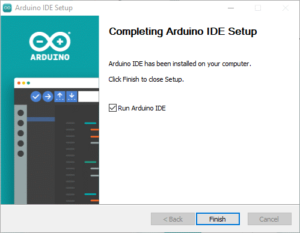
- Open the Arduino IDE (Integrated Development Environment) on your computer.
- Create a new sketch and copy-paste the code provided into the IDE.
- Make sure the correct Arduino board and port are selected under the “Tools” menu.
- Connect the relay module to the Arduino board using jumper wires. Ensure that the input pins of the relay module are connected to the appropriate digital pins of the Arduino, as specified in the circuit diagram.
- Connect the external device (motor, light bulb, etc.) to the relay module’s load terminals.
- Connect a separate power supply to the external device, if required.
- Double-check all connections to ensure they are secure and correct.
- Click the “Upload” button in the Arduino IDE to

