

27
Jun
Interfacing 1-Key Input Button to Control 1-LED
Project Overview: In this project, we will demonstrate how to interface a 1-key input button with an Arduino board to control the ON/OFF state of an LED. Each button press will toggle the LED’s state.
Hardware Required:
- Arduino board (e.g., Arduino Uno)
- 4-key input button module
- LED Module
- Jumper wires
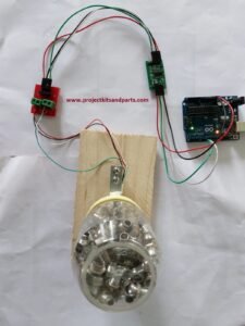
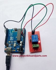
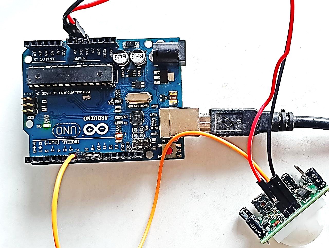
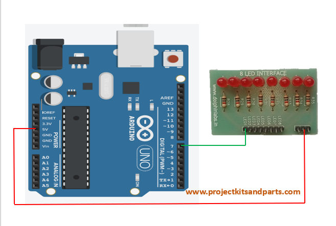
Circuit Diagram: Connect the components as follows:
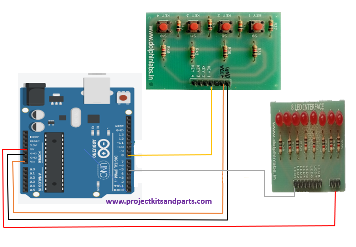
Note: The specific pin connections may vary depending on the type of 4-key input button module you have. Please refer to the datasheet or documentation of your button module for the appropriate connections.
Connection Table: Here’s a connection table for the button module, LED, and Arduino:
| Button Module Pin | Arduino Pin |
| Key1 VCC GND | Digital Pin (e.g., 8) Vin(vcc) GND |
| LED Module Pin | Arduino Pin |
| ledPin1 Vcc | Digital Pin (e.g., 5) 5v(vcc) |
Below is the Arduino code to control the LED using the key input button:
// Define the button module pins connected to the Arduin o
const int keyPin1 = 8;
// Define the LED pins connected to the Arduino
const int ledPin1 = 5;
void setup() {
// Set the button module pins as inputs
pinMode(keyPin1, INPUT_PULLUP);
// Set the LED pins as outputs
pinMode(ledPin1, OUTPUT);
}
void loop() {
// Read the button module pins
bool buttonState1 = digitalRead(keyPin1);
// Check if any button is pressed
if (buttonState1 == LOW) {
// If button 1 is pressed, turn on LED 1
digitalWrite(ledPin1, LOW);
delay(200);
} else {
// If no button is pressed, turn off all LEDs
digitalWrite(ledPin1, HIGH);
}
}
Code Explanation:
- The code defines the pins connected to the button module (keyPin1) and the LED pins (ledPin1).
- In the setup() function, the button module pins are set as inputs using pinMode(), and the LED pins are set as outputs.
- In the loop() function, the state of each button is read using digitalRead() and stored in respective variables (buttonState1, buttonState2, etc.).
- The code then checks which button is pressed by comparing the button states.
- If a button is pressed, the corresponding LED is turned on by setting its pin to LOW using digitalWrite(), and a delay of 200 milliseconds is added for debounce.
- If no button is pressed, all LEDs are turned off by setting their pins to HIGH.
- The code continuously loops and checks the button states, allowing the LEDs to be controlled based on the button presses.
Project Steps:
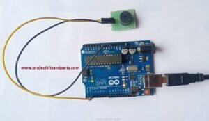
- Connect the Arduino board to your computer via USB.
- Open the Arduino IDE (Integrated Development Environment) on your computer.
- Create a new sketch and copy-paste the code provided into the IDE.
- Make sure the correct Arduino board and port are selected under the “Tools” menu.
- Click the “Upload” button to compile and upload the code to the Arduino board.
- Connect the 4-key input button module to the Arduino using the specified pin connections.
- Connect the LEDs to the Arduino’s digital pins specified in the connection table.
- When the code runs, pressing each button will turn on the corresponding LED, and releasing the button will turn off the LED.
- If no button is pressed, LED will be turned off.


