Interfacing Buzzer with Arduino Board
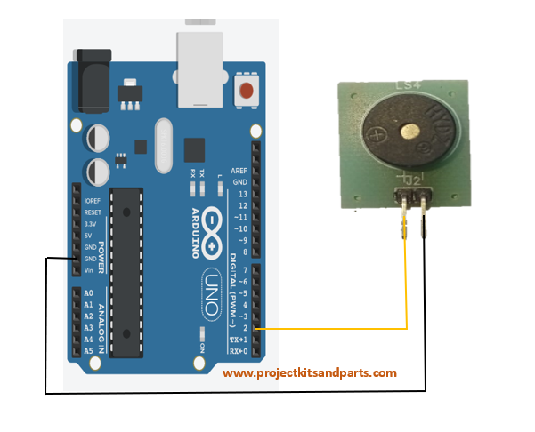
In this project, we will demonstrate how to interface a buzzer with an Arduino board. The buzzer will be used to generate sound or alert signals based on the Arduino’s control.
Hardware Required:
- Arduino board (e.g., Arduino Uno)
- Buzzer (passive or active)
- Jumper wires
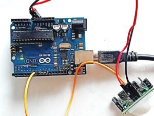
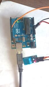
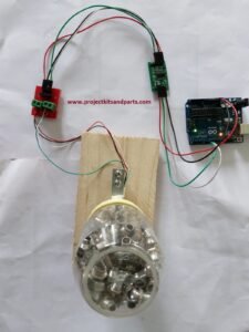
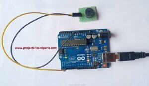
Circuit Diagram: Connect the components as follows:
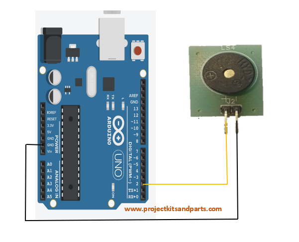
Connection Table: Here’s a connection table for the buzzer and Arduino:
| Buzzer | Arduino Board |
| Buzzer Pin GND | Digital Pin (e.g., 2) GND |
Below is the Arduino code to control the buzzer:
| //www.projectkitsandparts.com //Define the Arduino pin connected to the buzzer const int buzzerPin = 2; void setup() { // Set the buzzer pin as an output pinMode(buzzerPin, OUTPUT); } void loop() { // Generate a tone on the buzzer digitalWrite(buzzerPin, HIGH); delay(1000); // Stop the tone digitalWrite(buzzerPin, LOW); delay(1000); } |
Code Explanation:
- The buzzerPin variable is declared and set to the Arduino pin connected to the buzzer.
- In the setup() function, the buzzerPin is set as an output using the pinMode() function.
- The loop() function is where the buzzer control happens.
- The program waits for 1 second using delay(1000)
- The loop repeats, generating the tone and stopping it continuously.
Project Steps:
- Connect the Arduino board to your computer via USB.
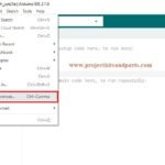
- Open the Arduino IDE (Integrated Development Environment) on your computer.
- Create a new sketch and copy-paste the code provided into the IDE.
- Make sure the correct Arduino board and port are selected under the “Tools” menu.
- Click the “Upload” button to compile and upload the code to the Arduino board.
- Connect the buzzer’s positive terminal (usually marked as “+” or “S”) to the specified Arduino pin.
- Connect the buzzer’s negative terminal (usually marked as “-” or “GND”) to the Arduino’s GND pin.
- When the code runs, the buzzer will generate a continuous tone with a frequency of 1000 Hz, followed by a 1-second pause, and then repeat.

