Interfacing a Single LED with ESP8266 Board
In this project, we will demonstrate how to interface a single LED (Light Emitting Diode) with an ESP8266 board.
The ESP8266 board will be programmed to control the LED and make it blink at a specific rate.
Hardware Required:
- ESP8266 board (e.g., NodeMCU )
- LED module
- Jumper wires
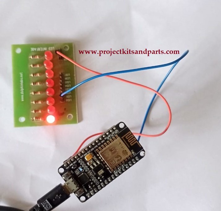
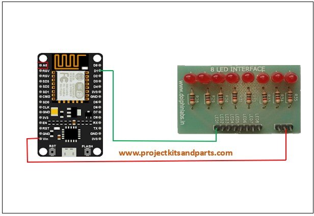
Connection Diagram:

Connections: ESP8266 Board Led Module 5V Vcc(5V) D1 Led pin 1
Code: Below is the Arduino code to control the LED:
// projectkitsandparts.com
// Define the pin connected to the LED
const int ledPin = 5;//D1
void setup() {
// Set the LED pin as an output
pinMode(ledPin, OUTPUT);
}
void loop() {
// Turn the LED on
digitalWrite(ledPin, HIGH);
// Wait for 1 second
delay(1000);
// Turn the LED off
digitalWrite(ledPin, LOW);
// Wait for 1 second
delay(1000);
}
Code Explanation:
- The ledPin variable is declared and set to 5, which corresponds to the GPIO pin connected to the LED on the ESP8266 board.
- In the setup() function, the ledPin is set as an output using the pinMode() function.
- The loop() function is where the LED control happens.
- The LED is turned on by setting the ledPin to HIGH using digitalWrite().
- The program waits for 1 second using delay(1000).
- The LED is turned off by setting the ledPin to LOW.
- Another 1-second delay is added.
- The loop repeats, toggling the LED on and off continuously.


