
Description
For Numato Products Price details/ quotation please mail your requirements on dolphinlabs17@gmail.com
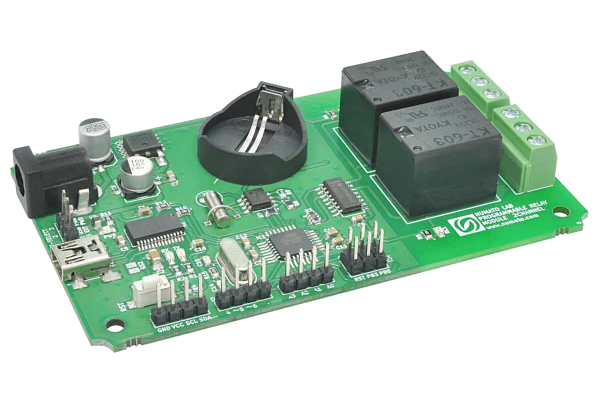
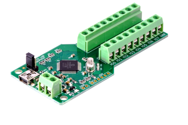
Numato Lab’s 2 Channel Programmable Relay Module is a feature-rich product that can be programmed with Arduino IDE. The USB to Serial Chip FT232RL helps to upload sketches quickly to the board. This programmability gives this board ultimate flexibility compared to other relay modules where features depend on the pre-programmed firmware. The onboard programmable relays, digital I/O’s, analog inputs, Real-Time Clock(RTC), and Micro SD memory card slot make this module useful for learning as well as making sophisticated applications.
Features
- Atmega328p Microcontroller with 32KBytes flash memory
- Arduino IDE Compatible
- FT232RL chip for USB – Serial Interface
- 2 SPDT 12V Mechanical Relays
- 4 Digital I/O’s
- 2 PWM outs
- 4 Analog Inputs
- I2C Interface
- Real-Time Clock(RTC)
- Battery backup for RTC
- Micro SD Card Slot
- LED indicators for Power, TX, RX and Relays
- ISP for programming custom boot loader/ firmware
- 16 MHz Crystal
- USB mini Connector for host communication
- Based on Arduino Duemilanove at arduino.cc
Applications
- Home Automation
- Lighting Control
- Garden Equipment Control
- Industrial Automation
- Test Fixtures
- DIY and Hobby
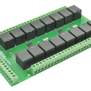
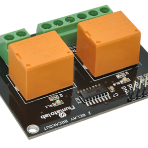
Related products
-
₹2,561.00
-

For quotation / Price Please send requirements on dolphinlabs17@gmail.com
₹43,499.00 -
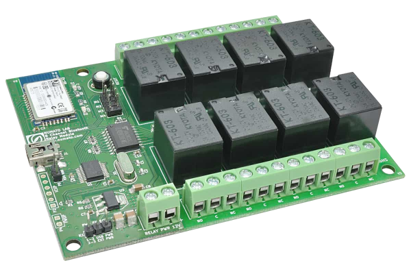 ₹6,295.00
 -
 ₹4,243.00
 -

-

