

Digital Thermometer


In Stock
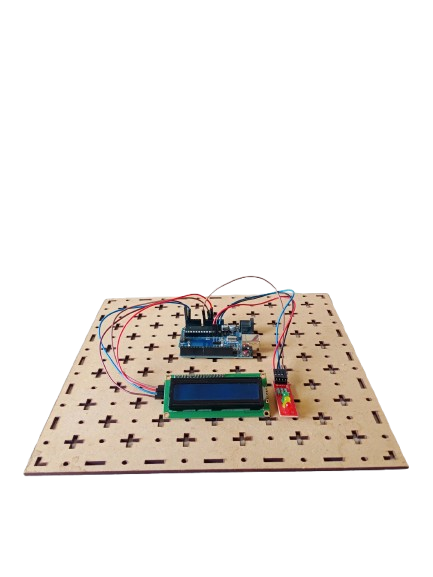
A digital thermometer project using the 8051 microcontroller involves interfacing a temperature sensor, like the LM35, with the microcontroller to measure temperature. The 8051 processes the sensor data and displays the temperature on LCD.
Description
A digital thermometer project using the 8051 microcontroller involves interfacing a temperature sensor, such as the LM35, with the microcontroller to measure temperature. The LM35 sensor provides an analog voltage output that is proportional to the temperature, which is then converted to a digital value by the 8051 microcontroller. The microcontroller processes this data and displays the temperature reading on an output device, such as an LCD screen. This project helps in understanding sensor interfacing, analog-to-digital conversion, and microcontroller programming, making it an excellent way to learn embedded systems and digital electronics.
Here are some key features of a digital thermometer project using the 8051 microcontroller:
1.Temperature Measurement: The LM35 sensor accurately measures temperature and provides an analog output proportional to the temperature.
2.Analog-to-Digital Conversion: The 8051 microcontroller reads the analog signal from the sensor and converts it to a digital format for processing.
3.Display Output: The temperature reading is displayed on an LCD or 7-segment display for easy viewing.
4.Low Power Consumption: The project typically uses low-power components, making it efficient for continuous operation.
5.User Interface: Can include simple buttons to reset or change the units of measurement (Celsius/Fahrenheit).
6.Accuracy: Provides reliable and accurate temperature readings with minimal calibration.
7.Simple Design: The project is relatively easy to build, making it suitable for beginners in embedded systems.
8.Cost-Effective: Utilizes affordable components like the 8051 microcontroller and the LM35 sensor.
9.Scalability: Can be expanded to include additional features like temperature logging or wireless communication.
-
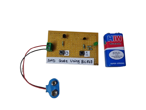
An AND gate can be built using BC547 NPN transistors, a common general-purpose transistor used in digital circuits.
The circuit represents both the inputs A & B for the AND gate and Output, Q, which also has a +5V supply to the collector of the first transistor, which is connected in series to the second transistor, and an LED is connected to the emitter terminal of the second transistor. The inputs A & B are connected to the base terminal of Transistor 1 and Transistor 2, respectively, and the output Q goes to the positive terminal LED.
₹190.00 -
₹2,561.00
-
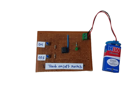
A Touch ON/OFF Switch is an electronic circuit that allows a device to be turned on or off by simply touching a sensor pad or wire, instead of using a mechanical switch. It works by detecting a small electrical signal from the human body (capacitive or resistive touch) and using that to toggle the output state.
These switches are commonly used in modern electronics, home automation, and DIY projects due to their durability, aesthetic appeal, and user-friendly operation.
₹150.00 -

-
A Traffic Light Signal is an electronic project designed to manage vehicle and pedestrian traffic at intersections. Using Arduino, LEDs (Red, Yellow, Green), and an LCD, the system simulates real-world traffic light behavior, displaying signal changes with appropriate timing. This project demonstrates traffic management, embedded system programming, and microcontroller-based automation.
-

Related products
-

A digital code lock system with a buzzer and servo motor is an embedded project that enhances security. When the correct code is entered, the microcontroller triggers a servo motor to unlock a door or container. If an incorrect code is entered, a buzzer sounds as an alert.
-

A fire detection system with a buzzer is an embedded project designed to enhance safety. When smoke or heat is detected, the microcontroller triggers a buzzer to sound an alarm, alerting people to the presence of a fire
-

- A rain alert system with an LCD display and buzzer, controlled by an 8051 microcontroller, is designed to detect rainfall and provide real-time notifications. The system uses a rain sensor to detect moisture or rainfall, and the microcontroller processes the sensor data. When rain is detected, the 8051 triggers a buzzer to alert the user audibly and displays the rain status on an LCD screen.
-

The Conveyor Belt Object Counter using LDR and 7-Segment Display with the 8051 microcontroller is designed to count objects passing in front of an LDR (Light Dependent Resistor) sensor. The system works by detecting light interruptions when an object crosses the sensor, causing a change in the LDR’s resistance. The microcontroller processes this change and increments an object count. The count is then displayed on a 7-segment display.
-

To measure distance using an ultrasonic sensor and display the result on an LCD with an 8051 microcontroller, you’ll need to interface several components: an ultrasonic sensor (e.g., HC-SR04), an LCD (e.g., 16×2), and the 8051 microcontroller.
-

This project involves controlling a DC motor’s direction using an 8051 microcontroller, with a buzzer and LED indicating the motor’s rotation state. When the DC motor rotates forward, the microcontroller keeps the buzzer and LED off. However, when the motor is rotated in reverse, the microcontroller triggers both the buzzer and LED to turn on as a visual and audible indication of the motor’s reverse rotation
