
Out Of Stock


Description
ELBERT V2 is a simple but versatile FPGA Learning/Development board featuring Xilinx Spartan 3A FPGA. An excellent choice for beginners and advanced learners for experimenting and learning system design with FPGAs. This development board features Xilinx XC3S50A 144 pin FPGA with a maximum of 108 user IOs (Some IOs are dedicated to system and peripherals). USB interface provides a fast and easy configuration download to the onboard SPI flash. You don’t need a programmer or special downloader cable to download bitstream to Elbert. ELBERT V2 features a stable clock source that is derived from the onboard configuration controller. ELBERT V2 incorporates LEDs, switches, and other peripherals for curious users to get started with the “Hello World” program in a matter of minutes.
Features
- FPGA: Spartan XC3S50A in TQG144 package
- Flash memory: 16 Mb SPI flash memory (M25P16)
- USB 2.0 interface for On-board flash programming
- FPGA configuration via JTAG and USB
- 8 LEDs, Six Push Buttons and 8 way DIP switch for user-defined application
- VGA output
- Stereo audio out
- Micro SD Card Adapter
- Three Seven Segment Displays
- 39 IOs for user-defined purposes
- On-board voltage regulators for single power rail operation
- RoHS Compliant
Applications
- Product Prototype Development
- Home Networking
- Signal Processing
- Wired and Wireless Communications
- Educational tool for schools and universities
-
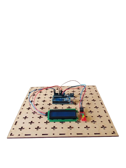
A Traffic Light Signal is an electronic project designed to manage vehicle and pedestrian traffic at intersections. Using Arduino, LEDs (Red, Yellow, Green), and an LCD, the system simulates real-world traffic light behavior, displaying signal changes with appropriate timing. This project demonstrates traffic management, embedded system programming, and microcontroller-based automation.
-
 ₹6,524.00
 -
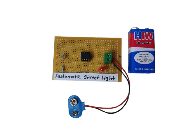
An Automatic Street Light using the IC 555 is a simple circuit that turns street lights ON at night and OFF during the day automatically. It uses a Light Dependent Resistor (LDR) to detect ambient light and a 555 Timer IC configured in comparator mode to control the switching.
₹175.00 -
-
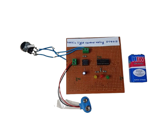
A traffic light control circuit using IC CD4017 is a simple digital electronics project that mimics the working of a real traffic light system. It uses the CD4017 decade counter IC along with a timer (usually 555 IC) to sequentially switch Red, Yellow, and Green LEDs, simulating the flow of traffic signals.
₹250.00 -
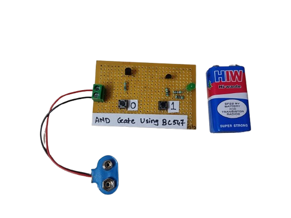
An AND gate can be built using BC547 NPN transistors, a common general-purpose transistor used in digital circuits.
The circuit represents both the inputs A & B for the AND gate and Output, Q, which also has a +5V supply to the collector of the first transistor, which is connected in series to the second transistor, and an LED is connected to the emitter terminal of the second transistor. The inputs A & B are connected to the base terminal of Transistor 1 and Transistor 2, respectively, and the output Q goes to the positive terminal LED.
₹190.00
Related products
-

For Numato Products Price details/ quotation please mail your requirements on dolphinlabs17@gmail.com
₹5,480.00 -

For Numato Products Price details/ quotation please mail your requirements on dolphinlabs17@gmail.com
₹4,245.00 -
 ₹7,321.00
 -
 ₹4,243.00
 -
 ₹4,745.00
 -
 ₹5,241.00