

Measure distance using Ultrasonic Sensor


In Stock
To measure distance using an ultrasonic sensor and display the result on an LCD with an 8051 microcontroller, you’ll need to interface several components: an ultrasonic sensor (e.g., HC-SR04), an LCD (e.g., 16×2), and the 8051 microcontroller.
Description
This project utilizes an ultrasonic sensor (HC-SR04) to measure distance and displays the result on a 16×2 LCD screen, controlled by an 8051 microcontroller. The HC-SR04 sensor works by emitting sound waves and calculating the time it takes for the sound to bounce back from an object. This time is then used to calculate the distance to the object, following the formula: Distance = (Time x Speed of Sound) / 2. The 8051 microcontroller processes this data, converts it into a readable format, and sends it to the LCD for display. The LCD shows the distance in centimeters or inches, providing an easy-to-read output for the user. This project demonstrates the integration of basic components such as sensors, microcontrollers, and display systems to solve real-world problems. It provides practical experience in programming the 8051 microcontroller, interfacing sensors, and using output devices like LCDs.
Applications of this project include:
1.Robotics: For obstacle detection and navigation in autonomous robots.
2.Distance Measurement: In applications like parking sensors for vehicles or industrial automation.
3.Level Sensing: In tanks or reservoirs to measure the height of liquid levels.
4.Security Systems: For monitoring distance in surveillance systems. This system can be extended to various fields like automation, automotive, and robotics.
-
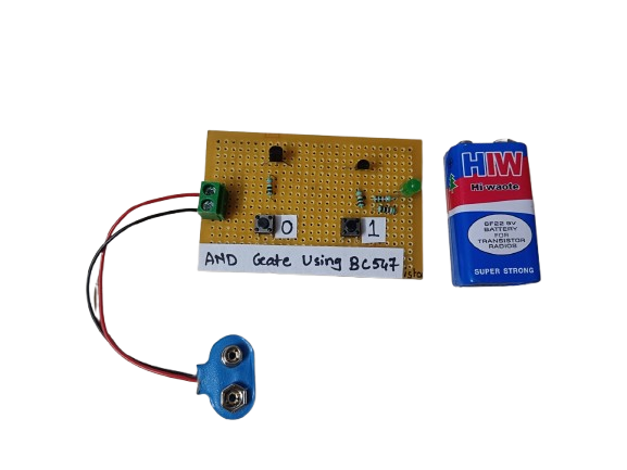
An AND gate can be built using BC547 NPN transistors, a common general-purpose transistor used in digital circuits.
The circuit represents both the inputs A & B for the AND gate and Output, Q, which also has a +5V supply to the collector of the first transistor, which is connected in series to the second transistor, and an LED is connected to the emitter terminal of the second transistor. The inputs A & B are connected to the base terminal of Transistor 1 and Transistor 2, respectively, and the output Q goes to the positive terminal LED.
₹190.00 -
For Numato Products Price details/ quotation please mail your requirements on dolphinlabs17@gmail.com
₹25,890.00 -
 ₹5,654.00
 -
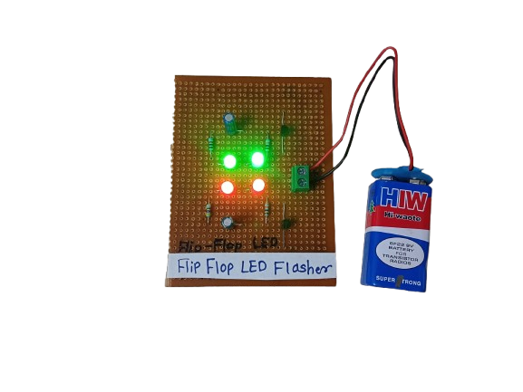
A Flip-Flop LED Flasher is a simple electronic circuit that alternately turns two LEDs on and off in a continuous loop, creating a blinking or “flashing” effect. It’s commonly built using transistors, resistors, capacitors, and LEDs, forming an astable multivibrator — a basic circuit that oscillates between two states without any external triggering.
It’s often used for decoration, indicators, or learning basic electronics.
₹175.00 -
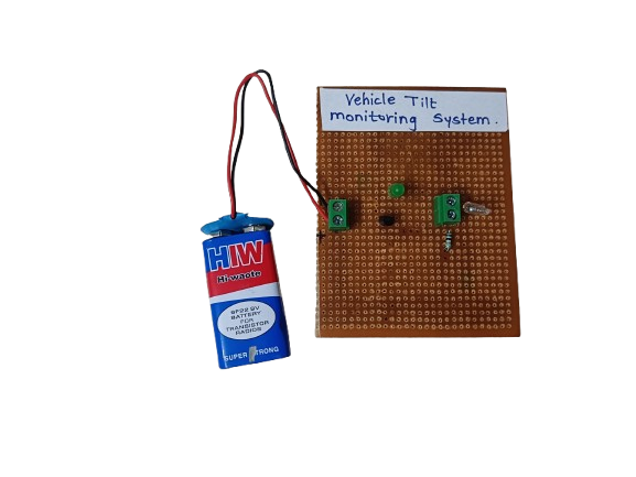
A Vehicle Tilt Monitoring System is an electronic safety system that detects abnormal tilting or leaning of a vehicle, such as when it is on a slope, at risk of tipping, or has experienced an impact. It alerts the driver or shuts down the system to prevent accidents.
₹185.00

Related products
-

- A rain alert system with an LCD display and buzzer, controlled by an 8051 microcontroller, is designed to detect rainfall and provide real-time notifications. The system uses a rain sensor to detect moisture or rainfall, and the microcontroller processes the sensor data. When rain is detected, the 8051 triggers a buzzer to alert the user audibly and displays the rain status on an LCD screen.
-

This project involves controlling a DC motor’s direction using an 8051 microcontroller, with a buzzer and LED indicating the motor’s rotation state. When the DC motor rotates forward, the microcontroller keeps the buzzer and LED off. However, when the motor is rotated in reverse, the microcontroller triggers both the buzzer and LED to turn on as a visual and audible indication of the motor’s reverse rotation
-

The Conveyor Belt Object Counter using LDR and 7-Segment Display with the 8051 microcontroller is designed to count objects passing in front of an LDR (Light Dependent Resistor) sensor. The system works by detecting light interruptions when an object crosses the sensor, causing a change in the LDR’s resistance. The microcontroller processes this change and increments an object count. The count is then displayed on a 7-segment display.
-

A digital code lock system with a buzzer and servo motor is an embedded project that enhances security. When the correct code is entered, the microcontroller triggers a servo motor to unlock a door or container. If an incorrect code is entered, a buzzer sounds as an alert.
-

A digital thermometer project using the 8051 microcontroller involves interfacing a temperature sensor, like the LM35, with the microcontroller to measure temperature. The 8051 processes the sensor data and displays the temperature on LCD.
-

A fire detection system with a buzzer is an embedded project designed to enhance safety. When smoke or heat is detected, the microcontroller triggers a buzzer to sound an alarm, alerting people to the presence of a fire
