


Description
For Numato Products Price details/ quotation please mail your requirements on dolphinlabs17@gmail.com
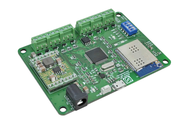
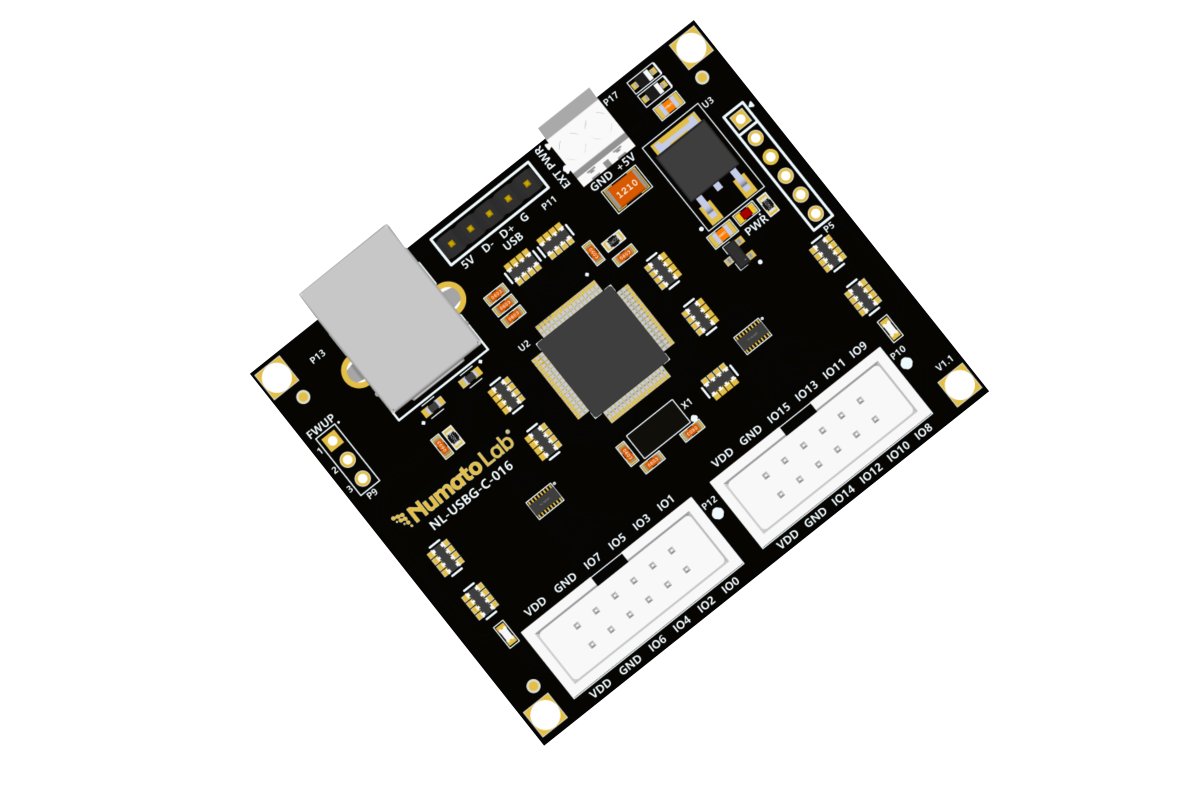
Mimas ECP5 Mini FPGA Development board is a simple FPGA board having Lattice ECP5 FPGA (LFE5U-45F-7BG256I package) with FTDI’s FT2232H Dual-Channel USB device. Lattice ECP5 FPGA family are renowned to break the rules of power, size and cost in your connectivity and acceleration applications. The USB 2.0 host interface based on popular FT2232H offers high bandwidth data transfer and board programming without the need for any external programming adapters.
Features
- Device: Lattice ECP5 FPGA (LFE5U-45F-7BG256I)
- DDR3: 2Gb DDR3 (MT41J128M16JT-125 or equivalent)
- Built-in programming interface. No expensive JTAG adapters needed for programming the board
- Onboard 128Mb flash memory for FPGA configuration storage and custom user data storage
- High-Speed USB 2.0 interface for On-board flash programming. FT2232H Channel B is dedicated for JTAG Programming. Channel A can be used for custom applications.
- 100mhz CMOS oscillator
- 8 LEDs, 1 RGB LED and 4 Push Buttons for user-defined purposes
- FPGA configuration via JTAG and USB
- Maximum IOs for user-defined purposes
- FPGA – 70 IOs (35 professionally length matched Differential Pairs) and two 2×6 Expansion Headers
Applications
- Product Prototype Development
- Accelerated computing integration
- Development and testing of custom embedded processors
- Communication devices development
- Educational tool for Schools and Universities
-

This project involves controlling a DC motor’s direction using an 8051 microcontroller, with a buzzer and LED indicating the motor’s rotation state. When the DC motor rotates forward, the microcontroller keeps the buzzer and LED off. However, when the motor is rotated in reverse, the microcontroller triggers both the buzzer and LED to turn on as a visual and audible indication of the motor’s reverse rotation
-


This project uses a PIC18F4550 microcontroller, an LM35 temperature sensor, and an LCD display to measure and display the ambient temperature.
-
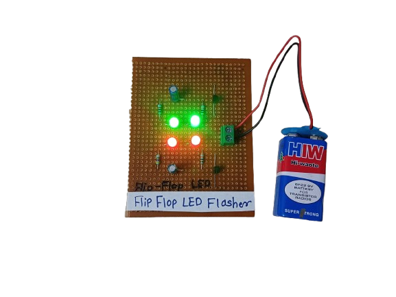
A Flip-Flop LED Flasher is a simple electronic circuit that alternately turns two LEDs on and off in a continuous loop, creating a blinking or “flashing” effect. It’s commonly built using transistors, resistors, capacitors, and LEDs, forming an astable multivibrator — a basic circuit that oscillates between two states without any external triggering.
It’s often used for decoration, indicators, or learning basic electronics.
₹175.00 -

For Numato Products Price details/ quotation please mail your requirements on dolphinlabs17@gmail.com
₹4,245.00 -
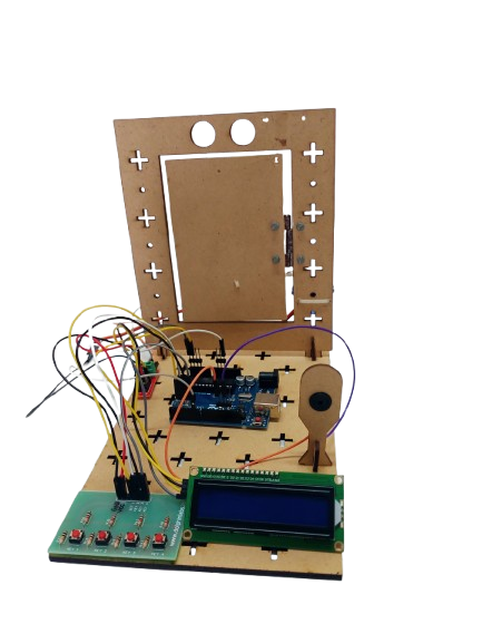
A Digital Lock System is an electronic security project designed to control access using a password entered via a keypad. It utilizes an Arduino, keypad, LCD, servo motor, and buzzer to provide a safe, automated locking mechanism. When the correct password is entered, the lock opens; if the wrong password is entered, an alert is triggered. This project is widely used in home security, lockers, safes, and access-controlled systems.
-
 ₹6,524.00
Related products
-

For quotation / Price Please send requirements on dolphinlabs17@gmail.com
₹43,499.00 -
 ₹10,401.00
 -

For Numato Products Price details/ quotation please mail your requirements on dolphinlabs17@gmail.com
₹5,480.00 -
-
 ₹7,321.00

