
Description
For Numato Products Price details/ quotation please mail your requirements on dolphinlabs17@gmail.com
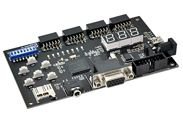
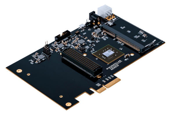
MIMAS V2 is a feature-packed yet low-cost FPGA Development board featuring AMD Spartan-6 FPGA. MIMAS V2 is specially designed for experimenting and learning system design with FPGAs. This development board features AMD SPARTAN XC6SLX9 CSG324 FPGA with onboard 512Mb DDR SDRAM. The USB 2.0 interface provides fast and easy configuration download to the onboard SPI flash. No need to buy an expensive programmer or special downloader cable to download the bitstream to the board.
Features
- FPGA: AMD Spartan XC6SLX9 in CSG324 package
- DDR Memory: 166MHz 512Mb LPDDR (MT46H32M16LF/W949D6CBHX6E)
- Flash memory: 16 Mb SPI flash memory (M25P16)
- USB 2.0 interface for On-board flash programming
- FPGA configuration via JTAG and USB
- 8 LEDs, Six Push Buttons, and 8 way DIP switch for user-defined purposes
- VGA Connector
- Stereo Jack
- Micro SD Card Adapter
- Three-Digit Seven Segment Displays
- 32 IOs for user-defined purposes
- Four 6×2 Expansion Connectors
- Onboard voltage regulators for single power rail operation
Applications
- Product Prototype Development
- Signal Processing
- Learning Digital Electronics
- Educational tool for schools and universities
-
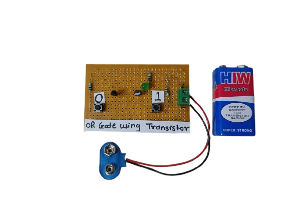
An OR gate using transistors is a basic logic circuit built using NPN transistors that performs the logical OR function. It gives a high output when at least one input is high. This is a fundamental building block in digital electronics and can be implemented using discrete components like transistors and resistors.
₹145.00 -
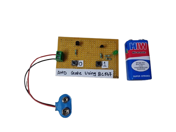
An AND gate can be built using BC547 NPN transistors, a common general-purpose transistor used in digital circuits.
The circuit represents both the inputs A & B for the AND gate and Output, Q, which also has a +5V supply to the collector of the first transistor, which is connected in series to the second transistor, and an LED is connected to the emitter terminal of the second transistor. The inputs A & B are connected to the base terminal of Transistor 1 and Transistor 2, respectively, and the output Q goes to the positive terminal LED.
₹190.00 -
 ₹136,940.00
 -
 ₹4,745.00
 -
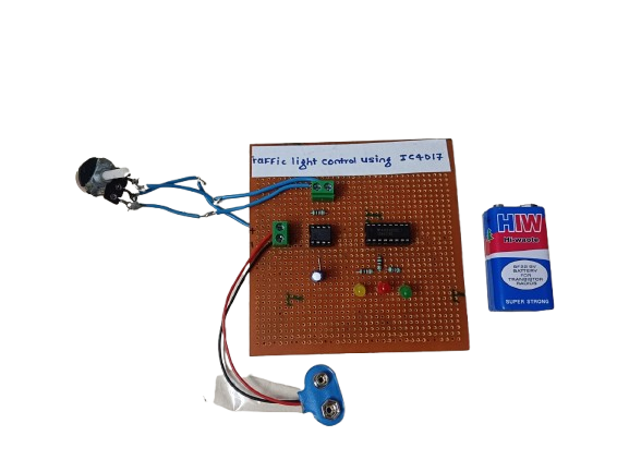
A traffic light control circuit using IC CD4017 is a simple digital electronics project that mimics the working of a real traffic light system. It uses the CD4017 decade counter IC along with a timer (usually 555 IC) to sequentially switch Red, Yellow, and Green LEDs, simulating the flow of traffic signals.
₹250.00 -

Related products
-
₹2,561.00
-
 ₹7,321.00
 -
 ₹5,241.00
 -

For Numato Products Price details/ quotation please mail your requirements on dolphinlabs17@gmail.com
₹4,245.00 -


