

NOR Gate using Transistors


₹150.00
In StockA NOR gate using transistors is a basic digital logic circuit that outputs HIGH (1) only when all inputs are LOW (0). It’s built by combining an OR gate followed by a NOT gate, using simple NPN transistors.
Description
The NOR gate (NOT-OR) is a fundamental logic gate used in digital electronics. It gives a LOW (0) output if any of its inputs are HIGH (1). If all inputs are LOW, the output is HIGH.
Building a NOR gate using transistors helps you understand how logic gates function at the hardware level. The circuit works by using NPN transistors to detect the presence of HIGH signals at the inputs. If either transistor receives a HIGH signal at its base, it conducts, pulling the output LOW.
If both inputs are LOW, neither transistor conducts, and the output is pulled HIGH through a pull-up resistor.
Applications:
1.Digital Circuits
1.Used in logic control, decision making, and microprocessor systems.
2.Combinational Logic Design
1.NOR gates are universal gates – any logic gate (AND, OR, NOT, XOR) can be built using only NOR gates.
3.Educational Projects
1.Useful for teaching logic gate basics with discrete components.
4.Simple Alarms and Control Circuits
1.NOR logic can control outputs based on multiple inputs.
-
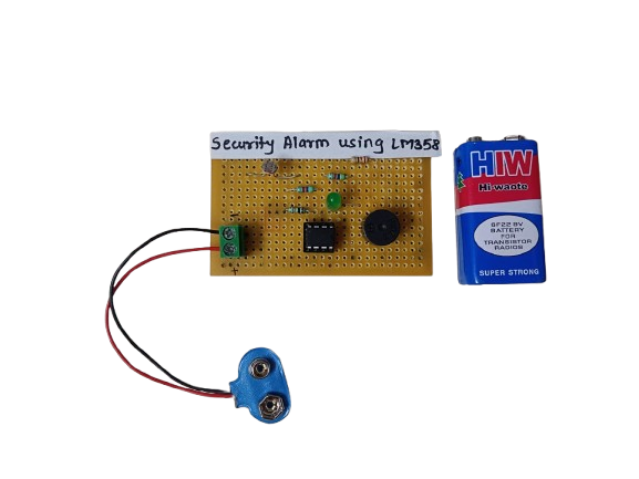
A Security Alarm Circuit using the LM358 IC is a simple yet effective system designed to trigger an alarm when unauthorized access or movement is detected. The LM358, a dual operational amplifier (Op-Amp), is used as a comparator to detect voltage changes from sensors like LDRs, IR sensors, or switches, and then activate a buzzer or relay.
₹200.00 -
₹4,825.00
-
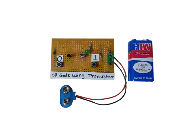
An OR gate using transistors is a basic logic circuit built using NPN transistors that performs the logical OR function. It gives a high output when at least one input is high. This is a fundamental building block in digital electronics and can be implemented using discrete components like transistors and resistors.
₹145.00 -

This project involves controlling a DC motor’s direction using an 8051 microcontroller, with a buzzer and LED indicating the motor’s rotation state. When the DC motor rotates forward, the microcontroller keeps the buzzer and LED off. However, when the motor is rotated in reverse, the microcontroller triggers both the buzzer and LED to turn on as a visual and audible indication of the motor’s reverse rotation
-
 ₹4,742.00
 -
 ₹10,401.00
Related products
-
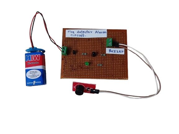
A Fire Detector Alarm is an electronic system designed to detect the presence of fire or high heat and trigger an audible or visual alarm. It typically uses sensors like thermistors, temperature sensors, or flame sensors to detect abnormal conditions indicating fire.
₹190.00 -
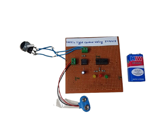
A traffic light control circuit using IC CD4017 is a simple digital electronics project that mimics the working of a real traffic light system. It uses the CD4017 decade counter IC along with a timer (usually 555 IC) to sequentially switch Red, Yellow, and Green LEDs, simulating the flow of traffic signals.
₹250.00 -
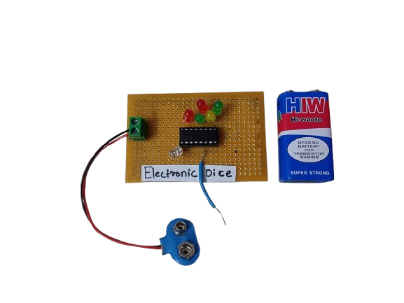
An Electronic Dice is a digital version of a traditional dice, which generates a random number (1 to 6) and displays it using LEDs or a 7-segment display. It uses components like a 555 timer, counter IC (like CD4017), or microcontrollers such as Arduino to simulate dice rolls electronically.
₹190.00 -
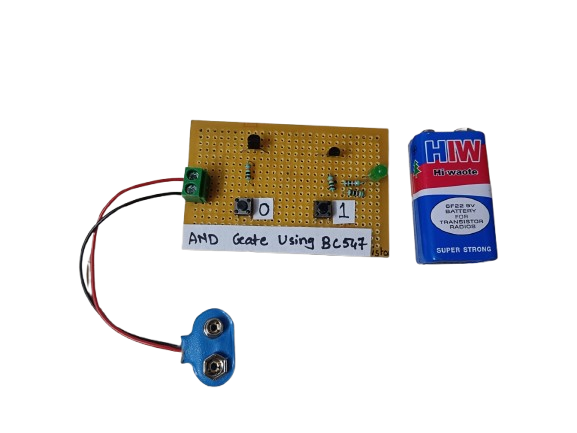
An AND gate can be built using BC547 NPN transistors, a common general-purpose transistor used in digital circuits.
The circuit represents both the inputs A & B for the AND gate and Output, Q, which also has a +5V supply to the collector of the first transistor, which is connected in series to the second transistor, and an LED is connected to the emitter terminal of the second transistor. The inputs A & B are connected to the base terminal of Transistor 1 and Transistor 2, respectively, and the output Q goes to the positive terminal LED.
₹190.00 -
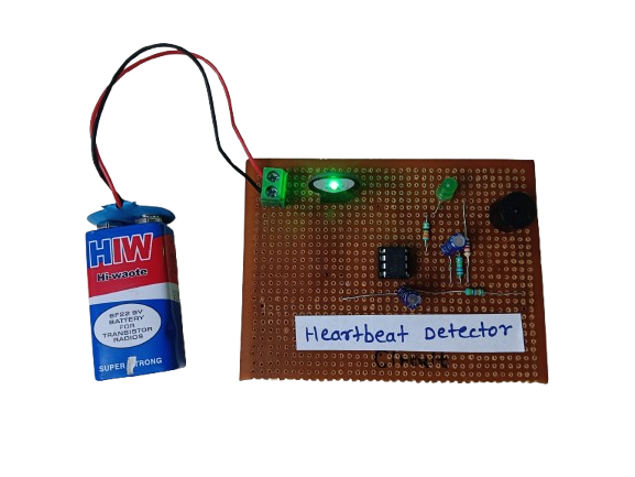
A heartbeat detector is an essential device for monitoring heart health, providing real-time data about a person’s pulse rate. Whether in a hospital, gym, or a DIY electronics project, it demonstrates how biomedical signals can be measured and processed using sensors and electronics. It’s a valuable tool for both personal health awareness and professional medical diagnostics.
₹450.00 -
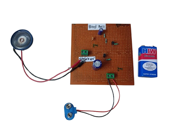
A Bird Bell is a device designed to either attract, entertain, or repel birds, depending on its purpose and context. Traditionally, it is a small bell-shaped object made of metal, ceramic, or wood, and is usually hung in gardens, balconies, farms, or near bird feeders. Its name comes from its interaction with birds — it may ring when birds land on it, brush past it, or when the wind causes it to move.
₹190.00
