

NOR Gate using Transistors


₹150.00
In StockA NOR gate using transistors is a basic digital logic circuit that outputs HIGH (1) only when all inputs are LOW (0). It’s built by combining an OR gate followed by a NOT gate, using simple NPN transistors.
Description
The NOR gate (NOT-OR) is a fundamental logic gate used in digital electronics. It gives a LOW (0) output if any of its inputs are HIGH (1). If all inputs are LOW, the output is HIGH.
Building a NOR gate using transistors helps you understand how logic gates function at the hardware level. The circuit works by using NPN transistors to detect the presence of HIGH signals at the inputs. If either transistor receives a HIGH signal at its base, it conducts, pulling the output LOW.
If both inputs are LOW, neither transistor conducts, and the output is pulled HIGH through a pull-up resistor.
Applications:
1.Digital Circuits
1.Used in logic control, decision making, and microprocessor systems.
2.Combinational Logic Design
1.NOR gates are universal gates – any logic gate (AND, OR, NOT, XOR) can be built using only NOR gates.
3.Educational Projects
1.Useful for teaching logic gate basics with discrete components.
4.Simple Alarms and Control Circuits
1.NOR logic can control outputs based on multiple inputs.
-
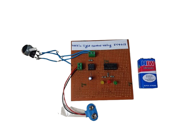
A traffic light control circuit using IC CD4017 is a simple digital electronics project that mimics the working of a real traffic light system. It uses the CD4017 decade counter IC along with a timer (usually 555 IC) to sequentially switch Red, Yellow, and Green LEDs, simulating the flow of traffic signals.
₹250.00 -
 ₹6,524.00
 -

The Conveyor Belt Object Counter using LDR and 7-Segment Display with the 8051 microcontroller is designed to count objects passing in front of an LDR (Light Dependent Resistor) sensor. The system works by detecting light interruptions when an object crosses the sensor, causing a change in the LDR’s resistance. The microcontroller processes this change and increments an object count. The count is then displayed on a 7-segment display.
-
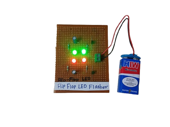
A Flip-Flop LED Flasher is a simple electronic circuit that alternately turns two LEDs on and off in a continuous loop, creating a blinking or “flashing” effect. It’s commonly built using transistors, resistors, capacitors, and LEDs, forming an astable multivibrator — a basic circuit that oscillates between two states without any external triggering.
It’s often used for decoration, indicators, or learning basic electronics.
₹175.00 -

A digital code lock system with a buzzer and servo motor is an embedded project that enhances security. When the correct code is entered, the microcontroller triggers a servo motor to unlock a door or container. If an incorrect code is entered, a buzzer sounds as an alert.
-

This project involves controlling a DC motor’s direction using an 8051 microcontroller, with a buzzer and LED indicating the motor’s rotation state. When the DC motor rotates forward, the microcontroller keeps the buzzer and LED off. However, when the motor is rotated in reverse, the microcontroller triggers both the buzzer and LED to turn on as a visual and audible indication of the motor’s reverse rotation
Related products
-
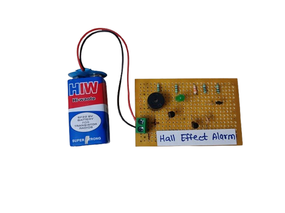
A Hall Effect Alarm is a type of security or position-detection system that uses a Hall Effect sensor to detect the presence or movement of a magnet. When the magnetic field changes (such as a magnet being removed or moved), the circuit triggers an alarm (buzzer, LED, relay, etc.).
₹210.00 -
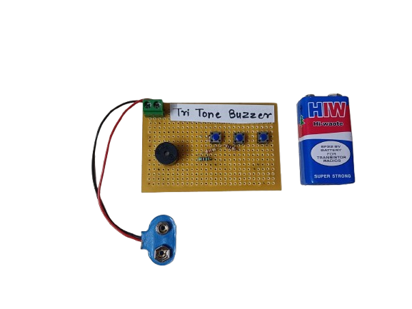
A Tri-Tone Buzzer is an audio signaling device that produces three distinct tones in a sequence or pattern. It’s commonly used in alarms, emergency systems, and attention-grabbing devices to indicate different conditions or alert levels.
₹180.00 -

A Water Level Indicator is an electronic device used to detect and display the level of water in a tank or reservoir. It helps prevent overflow and dry running of pumps by giving alerts or showing water levels in real time.
₹170.00 -
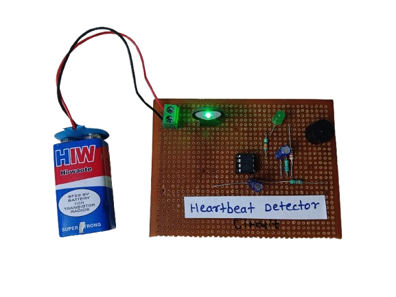
A heartbeat detector is an essential device for monitoring heart health, providing real-time data about a person’s pulse rate. Whether in a hospital, gym, or a DIY electronics project, it demonstrates how biomedical signals can be measured and processed using sensors and electronics. It’s a valuable tool for both personal health awareness and professional medical diagnostics.
₹450.00 -
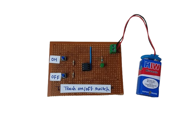
A Touch ON/OFF Switch is an electronic circuit that allows a device to be turned on or off by simply touching a sensor pad or wire, instead of using a mechanical switch. It works by detecting a small electrical signal from the human body (capacitive or resistive touch) and using that to toggle the output state.
These switches are commonly used in modern electronics, home automation, and DIY projects due to their durability, aesthetic appeal, and user-friendly operation.
₹150.00 -
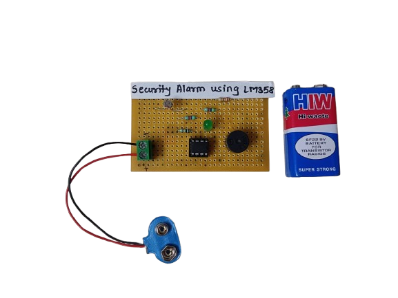
A Security Alarm Circuit using the LM358 IC is a simple yet effective system designed to trigger an alarm when unauthorized access or movement is detected. The LM358, a dual operational amplifier (Op-Amp), is used as a comparator to detect voltage changes from sensors like LDRs, IR sensors, or switches, and then activate a buzzer or relay.
₹200.00
