
New
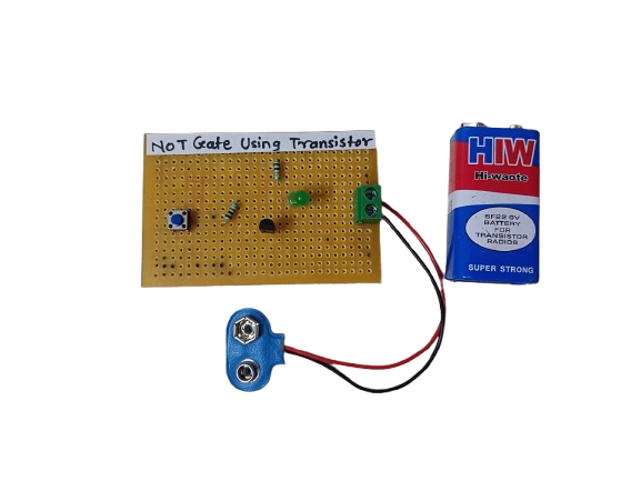
NOT Gate Using Transistor
In Stock
A NOT gate (or inverter) using a transistor is a simple digital logic circuit that outputs the opposite of the input signal. If the input is HIGH (1), the output is LOW (0), and vice versa. It’s built using a single NPN transistor and a few passive components.
Description
The NOT gate, also known as an inverter, is a fundamental digital logic gate that outputs the logical complement of its input. Implementing a NOT gate using a transistor is a basic and educational way to understand how logic gates function at the hardware level.
In a transistor-based NOT gate:
- When the input is HIGH (logic 1), the transistor turns ON, creating a path to ground, so the output is pulled LOW (logic 0).
- When the input is LOW (logic 0), the transistor remains OFF, and the output stays HIGH via a pull-up resistor.
Applications:
- Basic Logic Circuits
- Used in building more complex logic gates.
- Signal Inversion
- Inverts control signals in microcontroller or digital circuits.
- Microcontroller Interfaces
- Convert active-high signals to active-low and vice versa.
- Educational Purposes
- Demonstrates how digital logic works at the hardware level.
- Noise Filtering :-In some cases, helps clean up signals before processing.
Related products
-
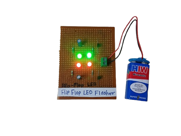
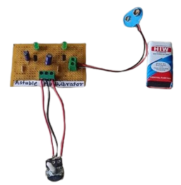
A Flip-Flop LED Flasher is a simple electronic circuit that alternately turns two LEDs on and off in a continuous loop, creating a blinking or “flashing” effect. It’s commonly built using transistors, resistors, capacitors, and LEDs, forming an astable multivibrator — a basic circuit that oscillates between two states without any external triggering.
It’s often used for decoration, indicators, or learning basic electronics.
₹175.00 -
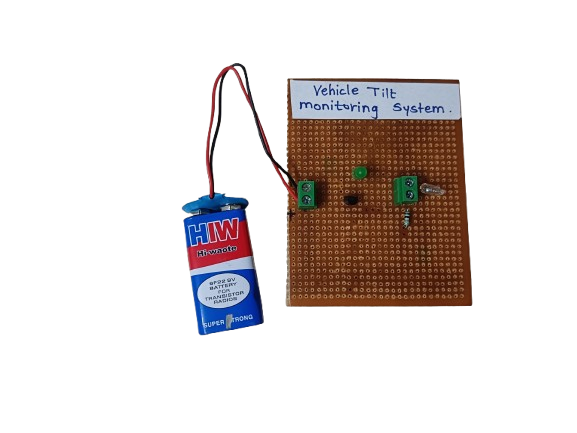
A Vehicle Tilt Monitoring System is an electronic safety system that detects abnormal tilting or leaning of a vehicle, such as when it is on a slope, at risk of tipping, or has experienced an impact. It alerts the driver or shuts down the system to prevent accidents.
₹185.00 -
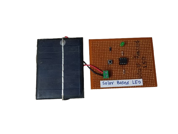
A solar-based LED system is a lighting setup that uses solar energy to power LED (Light Emitting Diode) lights. During the day, a solar panel captures sunlight and converts it into electrical energy, which is stored in a battery. At night or in low-light conditions, this stored energy powers the LED light.
These systems are eco-friendly, cost-effective, and ideal for off-grid or outdoor applications like street lighting, garden lights, and emergency lighting.
₹250.00 -
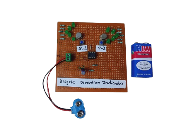
A Bicycle Direction Indicator is a safety system that uses LEDs or blinkers to signal the rider’s left or right turn intentions, just like car indicators. It’s often controlled by push buttons, switches, or microcontrollers.
₹180.00 -
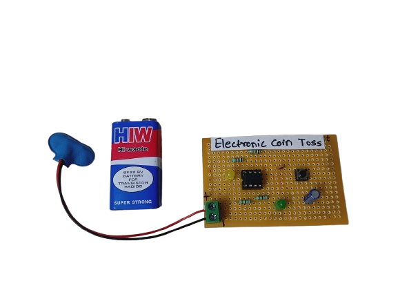
An Electronic Coin Toss circuit is an electronic version of the classic coin flip — often used to make quick decisions, settle disputes, or play games. It mimics the randomness of a real coin toss using digital logic or a microcontroller to generate a pseudo-random result and display it using LEDs or a text display (e.g., “Heads” or “Tails”).
₹160.00 -
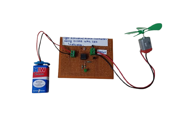
A Light Activated Motor Controller using IC 555 is a simple electronic circuit that turns a motor ON or OFF based on the presence or absence of light. It uses a LDR (Light Dependent Resistor) as a light sensor and the 555 timer IC in a comparator mode, along with an LED to indicate the motor’s status.
₹280.00