
New
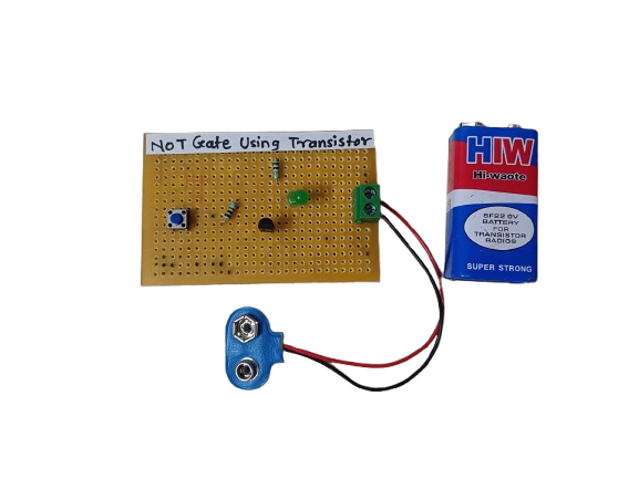
NOT Gate Using Transistor


In Stock
A NOT gate (or inverter) using a transistor is a simple digital logic circuit that outputs the opposite of the input signal. If the input is HIGH (1), the output is LOW (0), and vice versa. It’s built using a single NPN transistor and a few passive components.
Description
The NOT gate, also known as an inverter, is a fundamental digital logic gate that outputs the logical complement of its input. Implementing a NOT gate using a transistor is a basic and educational way to understand how logic gates function at the hardware level.
In a transistor-based NOT gate:
- When the input is HIGH (logic 1), the transistor turns ON, creating a path to ground, so the output is pulled LOW (logic 0).
- When the input is LOW (logic 0), the transistor remains OFF, and the output stays HIGH via a pull-up resistor.
Applications:
- Basic Logic Circuits
- Used in building more complex logic gates.
- Signal Inversion
- Inverts control signals in microcontroller or digital circuits.
- Microcontroller Interfaces
- Convert active-high signals to active-low and vice versa.
- Educational Purposes
- Demonstrates how digital logic works at the hardware level.
- Noise Filtering :-In some cases, helps clean up signals before processing.
Related products
-
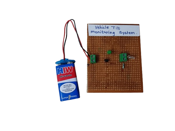
A Vehicle Tilt Monitoring System is an electronic safety system that detects abnormal tilting or leaning of a vehicle, such as when it is on a slope, at risk of tipping, or has experienced an impact. It alerts the driver or shuts down the system to prevent accidents.
₹185.00 -

An OR gate using transistors is a basic logic circuit built using NPN transistors that performs the logical OR function. It gives a high output when at least one input is high. This is a fundamental building block in digital electronics and can be implemented using discrete components like transistors and resistors.
₹145.00 -
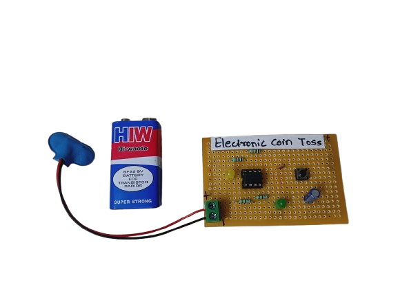
An Electronic Coin Toss circuit is an electronic version of the classic coin flip — often used to make quick decisions, settle disputes, or play games. It mimics the randomness of a real coin toss using digital logic or a microcontroller to generate a pseudo-random result and display it using LEDs or a text display (e.g., “Heads” or “Tails”).
₹160.00 -
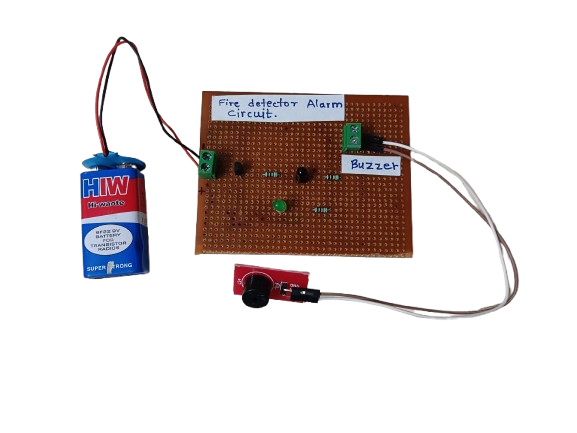
A Fire Detector Alarm is an electronic system designed to detect the presence of fire or high heat and trigger an audible or visual alarm. It typically uses sensors like thermistors, temperature sensors, or flame sensors to detect abnormal conditions indicating fire.
₹190.00 -
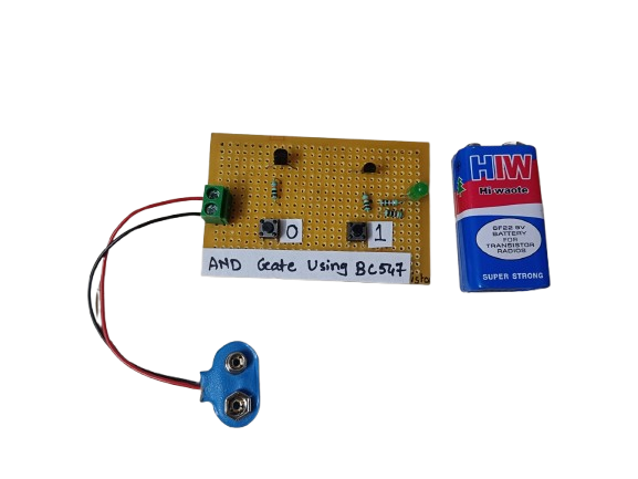
An AND gate can be built using BC547 NPN transistors, a common general-purpose transistor used in digital circuits.
The circuit represents both the inputs A & B for the AND gate and Output, Q, which also has a +5V supply to the collector of the first transistor, which is connected in series to the second transistor, and an LED is connected to the emitter terminal of the second transistor. The inputs A & B are connected to the base terminal of Transistor 1 and Transistor 2, respectively, and the output Q goes to the positive terminal LED.
₹190.00 -

An Electronic Dice is a digital version of a traditional dice, which generates a random number (1 to 6) and displays it using LEDs or a 7-segment display. It uses components like a 555 timer, counter IC (like CD4017), or microcontrollers such as Arduino to simulate dice rolls electronically.
₹190.00
