
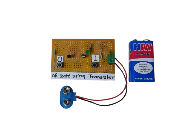
OR Gate using Transistors
₹145.00
In StockAn OR gate using transistors is a basic logic circuit built using NPN transistors that performs the logical OR function. It gives a high output when at least one input is high. This is a fundamental building block in digital electronics and can be implemented using discrete components like transistors and resistors.
Description
An OR gate is one of the fundamental logic gates used in digital electronics. It outputs a HIGH (1) signal if any one or both of its inputs are HIGH (1). While OR gates are usually found inside integrated circuits (like the 7432 IC), they can also be built using discrete NPN transistors to help students and beginners understand the working principles of logic gates at the component level.
In a typical transistor-based OR gate, each input controls a transistor. When either of the transistors is turned ON by a high input, it creates a conducting path that allows current to flow, resulting in a HIGH output. This setup clearly demonstrates the OR logic behavior using basic electronic components.
Such transistor-based logic gates are commonly used in educational circuits, basic digital electronics experiments, and custom logic designs where using ICs might not be necessary.
Applications of OR Gate Using Transistors:
1.Basic Digital Circuits – For learning and prototyping simple logic operations.
2.Custom Logic Control – In small DIY or embedded systems where ICs are unavailable.
3.Microcontroller Interfacing – Logic combination before feeding signals into a microcontroller.
4.Signal Detection Systems – Triggering output if any input condition is met.
5.Educational Projects – Used in physics/electronics labs to demonstrate logic gate behavior.
-
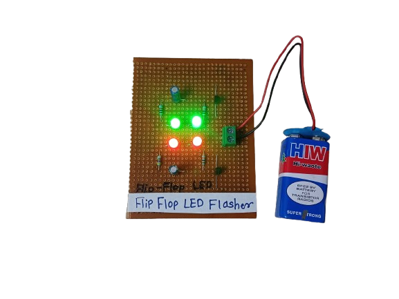
A Flip-Flop LED Flasher is a simple electronic circuit that alternately turns two LEDs on and off in a continuous loop, creating a blinking or “flashing” effect. It’s commonly built using transistors, resistors, capacitors, and LEDs, forming an astable multivibrator — a basic circuit that oscillates between two states without any external triggering.
It’s often used for decoration, indicators, or learning basic electronics.
₹175.00 -
For Numato Products Price details/ quotation please mail your requirements on dolphinlabs17@gmail.com
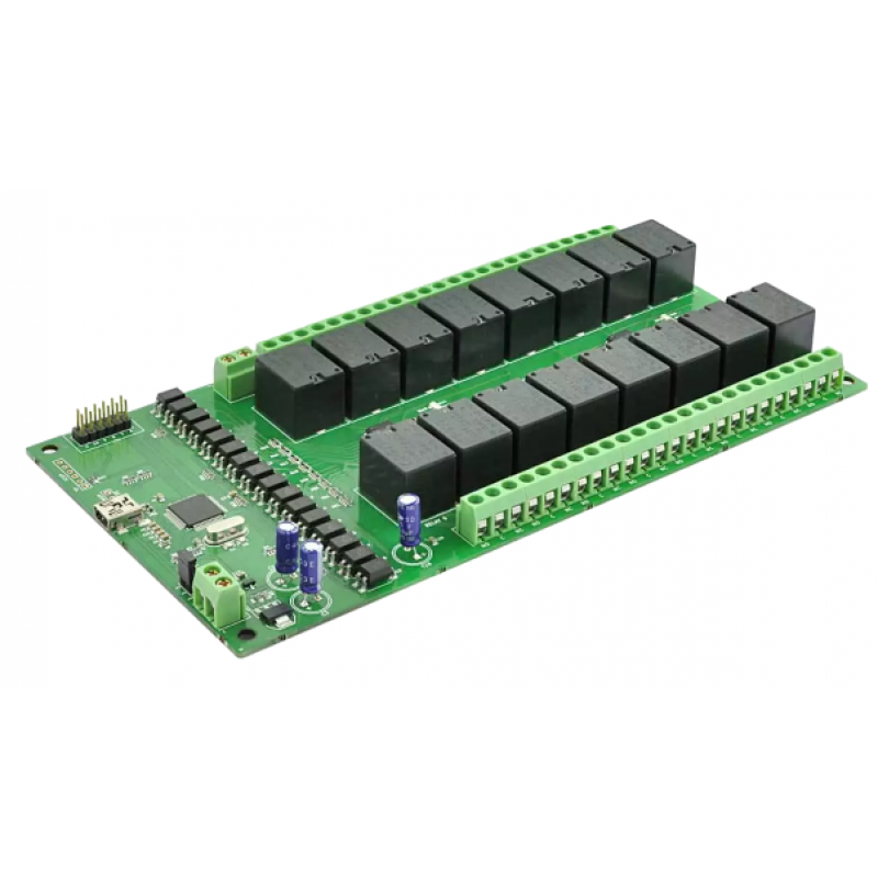
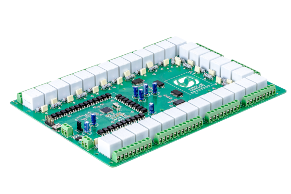
₹8,785.00 -

For Numato Products Price details/ quotation please mail your requirements on dolphinlabs17@gmail.com
₹5,480.00 -

Photo phobic robot will sense the light and will try to move away from light. On the contrary photo phobic is exactly opposite where it does not follow the light or more precisely it avoids and goes to places where there is less light
₹1,250.00 -
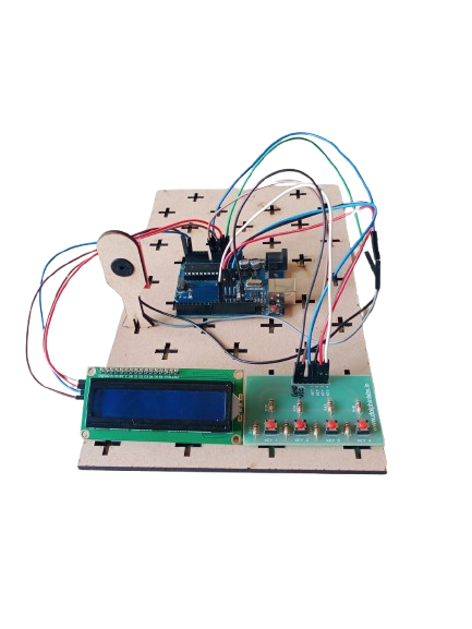
A Reaction Time Game is an interactive electronic project designed to measure a user’s response speed. Using an Arduino, keypad, buzzer, and LCD, the system tests how quickly a player can respond to a visual or auditory signal. This project is widely used in educational setups, gaming, and psychology experiments to study reflexes and reaction times.
-
 ₹16,260.00
Related products
-
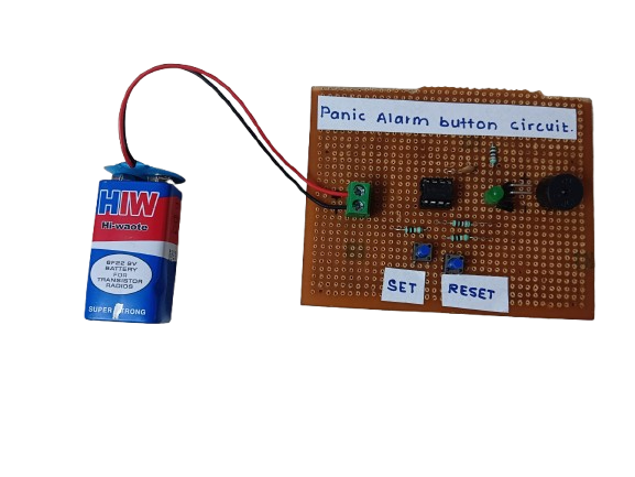
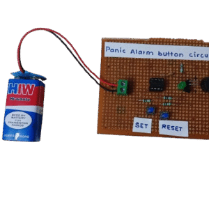
A Panic Alarm Button is a simple safety device that, when pressed, immediately activates a loud alarm, buzzer, or alert system to signal an emergency or request for help. It’s commonly used in homes, banks, hospitals, and personal security systems.
₹160.00 -
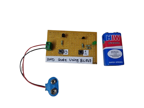
An AND gate can be built using BC547 NPN transistors, a common general-purpose transistor used in digital circuits.
The circuit represents both the inputs A & B for the AND gate and Output, Q, which also has a +5V supply to the collector of the first transistor, which is connected in series to the second transistor, and an LED is connected to the emitter terminal of the second transistor. The inputs A & B are connected to the base terminal of Transistor 1 and Transistor 2, respectively, and the output Q goes to the positive terminal LED.
₹190.00 -
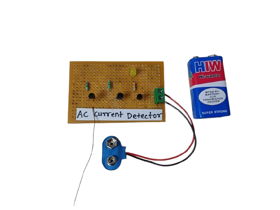
An AC Current Detector is a device or circuit that senses the flow of alternating current (AC) through a wire or appliance. It typically uses components like a current transformer (CT) or hall effect sensor to detect AC current and activate an indicator such as an LED or buzzer.
₹180.00 -
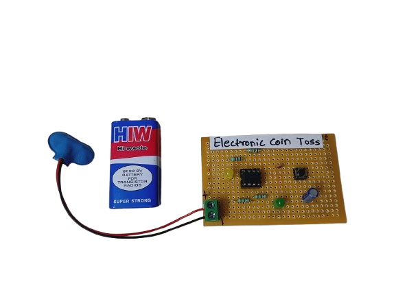
An Electronic Coin Toss circuit is an electronic version of the classic coin flip — often used to make quick decisions, settle disputes, or play games. It mimics the randomness of a real coin toss using digital logic or a microcontroller to generate a pseudo-random result and display it using LEDs or a text display (e.g., “Heads” or “Tails”).
₹160.00 -
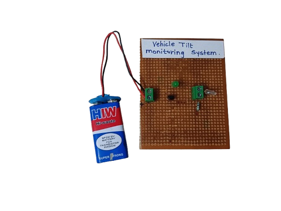
A Vehicle Tilt Monitoring System is an electronic safety system that detects abnormal tilting or leaning of a vehicle, such as when it is on a slope, at risk of tipping, or has experienced an impact. It alerts the driver or shuts down the system to prevent accidents.
₹185.00 -
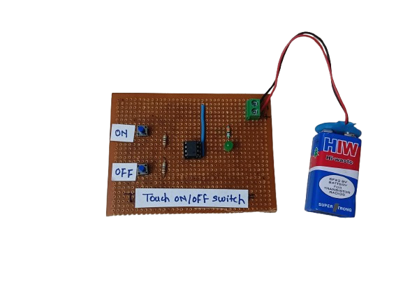
A Touch ON/OFF Switch is an electronic circuit that allows a device to be turned on or off by simply touching a sensor pad or wire, instead of using a mechanical switch. It works by detecting a small electrical signal from the human body (capacitive or resistive touch) and using that to toggle the output state.
These switches are commonly used in modern electronics, home automation, and DIY projects due to their durability, aesthetic appeal, and user-friendly operation.
₹150.00
