
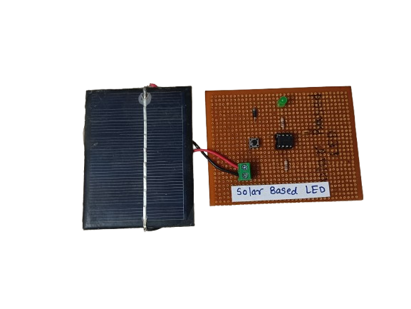
Solar Based LED Lighting System
₹250.00
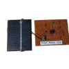
In StockA solar-based LED system is a lighting setup that uses solar energy to power LED (Light Emitting Diode) lights. During the day, a solar panel captures sunlight and converts it into electrical energy, which is stored in a battery. At night or in low-light conditions, this stored energy powers the LED light.
These systems are eco-friendly, cost-effective, and ideal for off-grid or outdoor applications like street lighting, garden lights, and emergency lighting.
Description
A solar-based LED lighting system combines two modern technologies: solar photovoltaic energy and LED lighting. It is a self-sustaining lighting solution that reduces reliance on grid electricity and promotes the use of renewable energy.
The system typically includes:
- A solar panel to collect sunlight and convert it into DC electricity.
- A rechargeable battery (usually lithium-ion or lead-acid) to store the energy.
- An LED lamp, known for its low power consumption, long lifespan, and high efficiency.
- A charge controller to regulate the flow of electricity between the panel, battery, and LED light.
When sunlight is available, the solar panel charges the battery. At night or during cloudy weather, the LED lamp draws power from the battery to provide illumination. Many systems also include automatic dusk-to-dawn sensors, which turn the light on/off based on ambient light levels.
Solar-powered LEDs are especially useful in remote areas where grid power is unavailable or unreliable. They offer a sustainable, low-maintenance, and energy-efficient alternative to traditional lighting systems.
Related products
-

A Water Level Indicator is an electronic device used to detect and display the level of water in a tank or reservoir. It helps prevent overflow and dry running of pumps by giving alerts or showing water levels in real time.
₹170.00 -
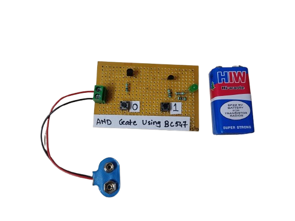
An AND gate can be built using BC547 NPN transistors, a common general-purpose transistor used in digital circuits.
The circuit represents both the inputs A & B for the AND gate and Output, Q, which also has a +5V supply to the collector of the first transistor, which is connected in series to the second transistor, and an LED is connected to the emitter terminal of the second transistor. The inputs A & B are connected to the base terminal of Transistor 1 and Transistor 2, respectively, and the output Q goes to the positive terminal LED.
₹190.00 -
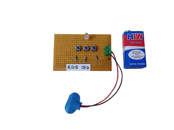
An RGB LED is a light-emitting diode that combines Red, Green, and Blue LEDs in a single package. By adjusting the brightness of each color, it can produce millions of colors, making it ideal for decorative lighting, displays, and indicators.
₹140.00 -
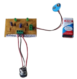

An Astable Multivibrator is an electronic oscillator circuit that continuously switches between two states without any external triggering. It produces a continuous square wave, making it ideal for generating clock pulses, timing signals, and blinking LEDs.
-
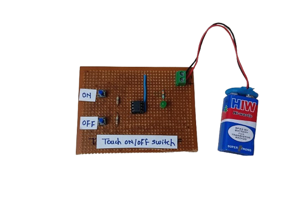
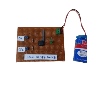
A Touch ON/OFF Switch is an electronic circuit that allows a device to be turned on or off by simply touching a sensor pad or wire, instead of using a mechanical switch. It works by detecting a small electrical signal from the human body (capacitive or resistive touch) and using that to toggle the output state.
These switches are commonly used in modern electronics, home automation, and DIY projects due to their durability, aesthetic appeal, and user-friendly operation.
₹150.00 -
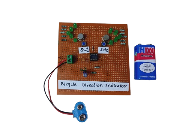
A Bicycle Direction Indicator is a safety system that uses LEDs or blinkers to signal the rider’s left or right turn intentions, just like car indicators. It’s often controlled by push buttons, switches, or microcontrollers.
₹180.00