
Traffic light control circuit using IC CD4017
₹250.00
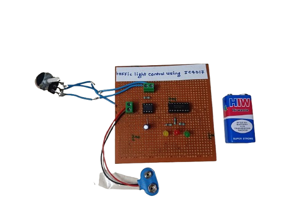
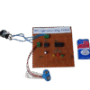
In StockA traffic light control circuit using IC CD4017 is a simple digital electronics project that mimics the working of a real traffic light system. It uses the CD4017 decade counter IC along with a timer (usually 555 IC) to sequentially switch Red, Yellow, and Green LEDs, simulating the flow of traffic signals.
Description
The CD4017 is a CMOS Decade Counter/Divider IC with 10 decoded outputs (Q0 to Q9). It is widely used in sequential control applications. When combined with a 555 timer IC (configured in astable mode), it forms the basis for a traffic light control system.
Here’s how the circuit works:
- The 555 timer generates a continuous clock pulse (square wave).
- These pulses are fed into the CD4017, which advances its output from Q0 to Q9 one by one with each clock pulse.
- By connecting Red, Yellow, and Green LEDs to specific outputs (like Q0, Q1, Q2), you can simulate a traffic light sequence.
- The timing of each light can be controlled by adjusting the resistor-capacitor (RC) values of the 555 timer.
The system repeats in a loop, much like actual traffic signals, but simplified for demonstration purposes.
Related products
-
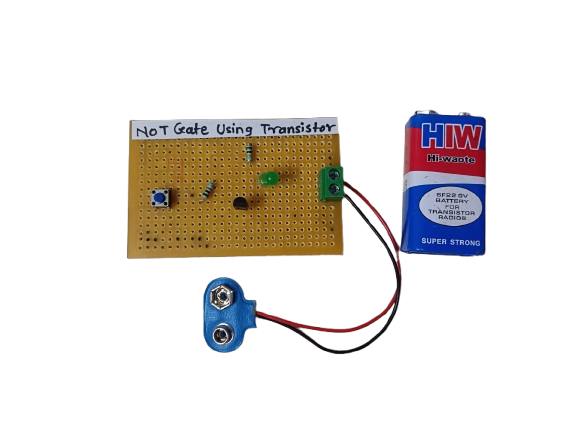
A NOR gate using transistors is a basic digital logic circuit that outputs HIGH (1) only when all inputs are LOW (0). It’s built by combining an OR gate followed by a NOT gate, using simple NPN transistors.
₹150.00 -
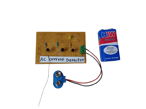
An AC Current Detector is a device or circuit that senses the flow of alternating current (AC) through a wire or appliance. It typically uses components like a current transformer (CT) or hall effect sensor to detect AC current and activate an indicator such as an LED or buzzer.
₹180.00 -
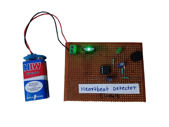
A heartbeat detector is an essential device for monitoring heart health, providing real-time data about a person’s pulse rate. Whether in a hospital, gym, or a DIY electronics project, it demonstrates how biomedical signals can be measured and processed using sensors and electronics. It’s a valuable tool for both personal health awareness and professional medical diagnostics.
₹450.00 -

A Water Level Indicator is an electronic device used to detect and display the level of water in a tank or reservoir. It helps prevent overflow and dry running of pumps by giving alerts or showing water levels in real time.
₹170.00 -
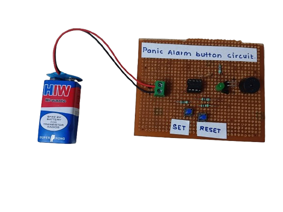
A Panic Alarm Button is a simple safety device that, when pressed, immediately activates a loud alarm, buzzer, or alert system to signal an emergency or request for help. It’s commonly used in homes, banks, hospitals, and personal security systems.
₹160.00 -
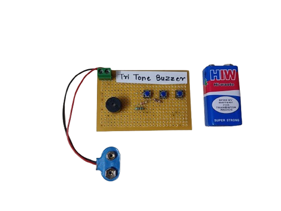
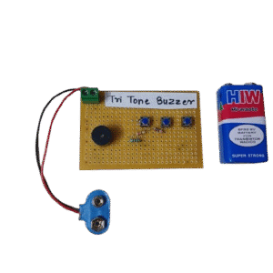
A Tri-Tone Buzzer is an audio signaling device that produces three distinct tones in a sequence or pattern. It’s commonly used in alarms, emergency systems, and attention-grabbing devices to indicate different conditions or alert levels.
₹180.00