

Traffic light control circuit using IC CD4017


₹250.00
In StockA traffic light control circuit using IC CD4017 is a simple digital electronics project that mimics the working of a real traffic light system. It uses the CD4017 decade counter IC along with a timer (usually 555 IC) to sequentially switch Red, Yellow, and Green LEDs, simulating the flow of traffic signals.
Description
The CD4017 is a CMOS Decade Counter/Divider IC with 10 decoded outputs (Q0 to Q9). It is widely used in sequential control applications. When combined with a 555 timer IC (configured in astable mode), it forms the basis for a traffic light control system.
Here’s how the circuit works:
- The 555 timer generates a continuous clock pulse (square wave).
- These pulses are fed into the CD4017, which advances its output from Q0 to Q9 one by one with each clock pulse.
- By connecting Red, Yellow, and Green LEDs to specific outputs (like Q0, Q1, Q2), you can simulate a traffic light sequence.
- The timing of each light can be controlled by adjusting the resistor-capacitor (RC) values of the 555 timer.
The system repeats in a loop, much like actual traffic signals, but simplified for demonstration purposes.
-

A Soil Moisture Detection System using Arduino, a soil moisture sensor, and a buzzer that sounds an alert when soil moisture is detected.
-
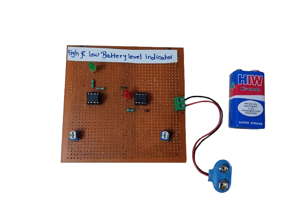
A Battery High-Low Monitor is an electronic circuit or device that detects and indicates the voltage level of a battery — whether it’s too high (overcharged), normal, or too low (discharged). It helps protect batteries from overcharging or deep discharge, which can damage the battery or reduce its lifespan.
These monitors often use comparators, voltage dividers, LED indicators, or microcontrollers to track and display battery status in real time.
₹225.00 -
 ₹12,480.00
 -
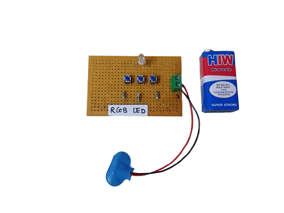
An RGB LED is a light-emitting diode that combines Red, Green, and Blue LEDs in a single package. By adjusting the brightness of each color, it can produce millions of colors, making it ideal for decorative lighting, displays, and indicators.
₹140.00 -
 ₹82,650.00
 -
 ₹52,199.00
Related products
-
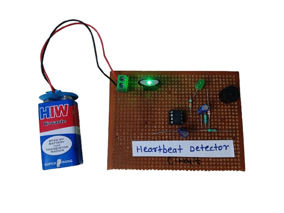
A heartbeat detector is an essential device for monitoring heart health, providing real-time data about a person’s pulse rate. Whether in a hospital, gym, or a DIY electronics project, it demonstrates how biomedical signals can be measured and processed using sensors and electronics. It’s a valuable tool for both personal health awareness and professional medical diagnostics.
₹450.00 -
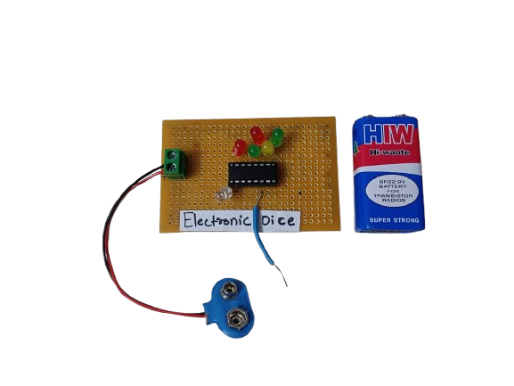
An Electronic Dice is a digital version of a traditional dice, which generates a random number (1 to 6) and displays it using LEDs or a 7-segment display. It uses components like a 555 timer, counter IC (like CD4017), or microcontrollers such as Arduino to simulate dice rolls electronically.
₹190.00 -
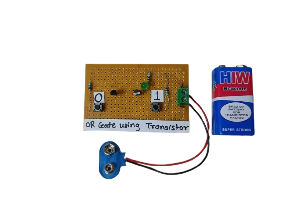
An OR gate using transistors is a basic logic circuit built using NPN transistors that performs the logical OR function. It gives a high output when at least one input is high. This is a fundamental building block in digital electronics and can be implemented using discrete components like transistors and resistors.
₹145.00 -
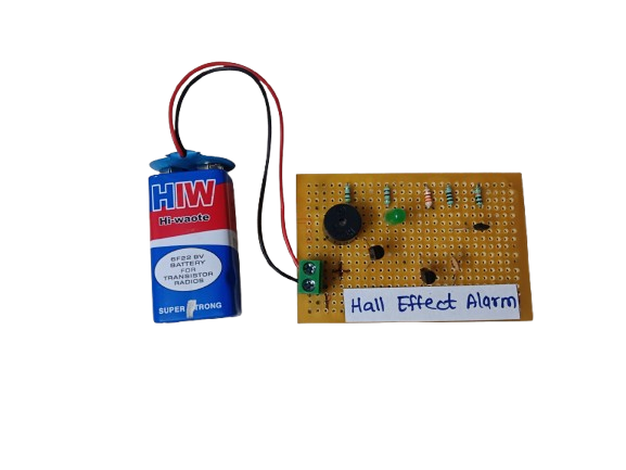
A Hall Effect Alarm is a type of security or position-detection system that uses a Hall Effect sensor to detect the presence or movement of a magnet. When the magnetic field changes (such as a magnet being removed or moved), the circuit triggers an alarm (buzzer, LED, relay, etc.).
₹210.00 -
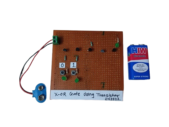
An XOR (Exclusive OR) gate is a digital logic gate that outputs true (1) only when the number of true inputs is odd. For two inputs, the output is high when the inputs are different. XOR gates can be constructed using basic logic gates or directly with transistors (BJT or MOSFET). Using transistors, we can design compact, efficient circuits for custom digital logic applications.
₹160.00 -
A Battery High-Low Monitor is an electronic circuit or device that detects and indicates the voltage level of a battery — whether it’s too high (overcharged), normal, or too low (discharged). It helps protect batteries from overcharging or deep discharge, which can damage the battery or reduce its lifespan.
These monitors often use comparators, voltage dividers, LED indicators, or microcontrollers to track and display battery status in real time.
₹225.00
