

Traffic light control circuit using IC CD4017


₹250.00
In StockA traffic light control circuit using IC CD4017 is a simple digital electronics project that mimics the working of a real traffic light system. It uses the CD4017 decade counter IC along with a timer (usually 555 IC) to sequentially switch Red, Yellow, and Green LEDs, simulating the flow of traffic signals.
Description
The CD4017 is a CMOS Decade Counter/Divider IC with 10 decoded outputs (Q0 to Q9). It is widely used in sequential control applications. When combined with a 555 timer IC (configured in astable mode), it forms the basis for a traffic light control system.
Here’s how the circuit works:
- The 555 timer generates a continuous clock pulse (square wave).
- These pulses are fed into the CD4017, which advances its output from Q0 to Q9 one by one with each clock pulse.
- By connecting Red, Yellow, and Green LEDs to specific outputs (like Q0, Q1, Q2), you can simulate a traffic light sequence.
- The timing of each light can be controlled by adjusting the resistor-capacitor (RC) values of the 555 timer.
The system repeats in a loop, much like actual traffic signals, but simplified for demonstration purposes.
-

The Conveyor Belt Object Counter using LDR and 7-Segment Display with the 8051 microcontroller is designed to count objects passing in front of an LDR (Light Dependent Resistor) sensor. The system works by detecting light interruptions when an object crosses the sensor, causing a change in the LDR’s resistance. The microcontroller processes this change and increments an object count. The count is then displayed on a 7-segment display.
-
-

A Water Level Indicator is an electronic device used to detect and display the level of water in a tank or reservoir. It helps prevent overflow and dry running of pumps by giving alerts or showing water levels in real time.
₹170.00 -
 ₹16,260.00
 -
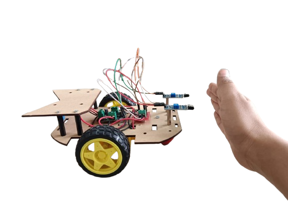
The basic function of this robot is simple, it follows object. It goes forward as you go forward; goes backward as you go backward; turns left/right as you turn left/right.
₹1,250.00

Related products
-
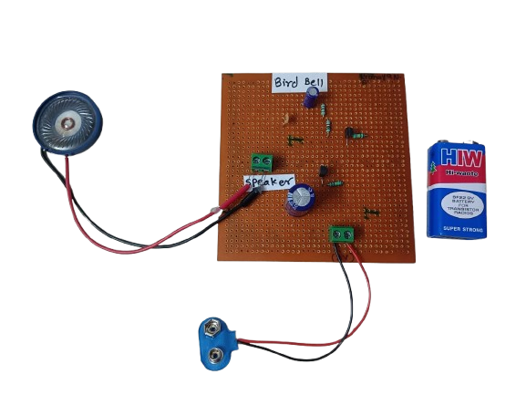
A Bird Bell is a device designed to either attract, entertain, or repel birds, depending on its purpose and context. Traditionally, it is a small bell-shaped object made of metal, ceramic, or wood, and is usually hung in gardens, balconies, farms, or near bird feeders. Its name comes from its interaction with birds — it may ring when birds land on it, brush past it, or when the wind causes it to move.
₹190.00 -
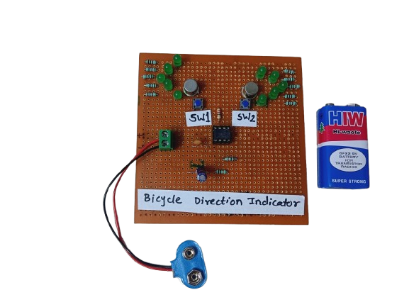
A Bicycle Direction Indicator is a safety system that uses LEDs or blinkers to signal the rider’s left or right turn intentions, just like car indicators. It’s often controlled by push buttons, switches, or microcontrollers.
₹180.00 -
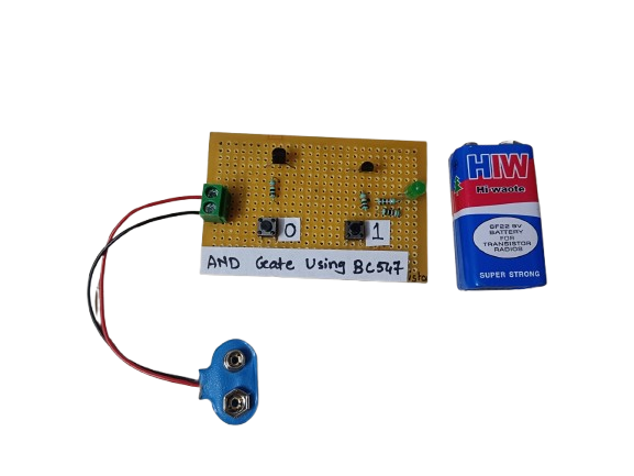
An AND gate can be built using BC547 NPN transistors, a common general-purpose transistor used in digital circuits.
The circuit represents both the inputs A & B for the AND gate and Output, Q, which also has a +5V supply to the collector of the first transistor, which is connected in series to the second transistor, and an LED is connected to the emitter terminal of the second transistor. The inputs A & B are connected to the base terminal of Transistor 1 and Transistor 2, respectively, and the output Q goes to the positive terminal LED.
₹190.00 -
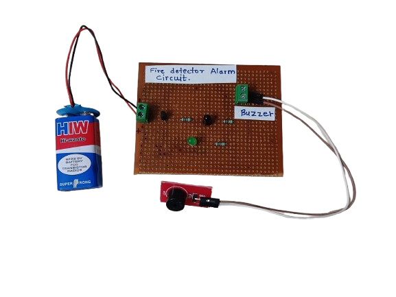
A Fire Detector Alarm is an electronic system designed to detect the presence of fire or high heat and trigger an audible or visual alarm. It typically uses sensors like thermistors, temperature sensors, or flame sensors to detect abnormal conditions indicating fire.
₹190.00 -
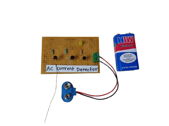
An AC Current Detector is a device or circuit that senses the flow of alternating current (AC) through a wire or appliance. It typically uses components like a current transformer (CT) or hall effect sensor to detect AC current and activate an indicator such as an LED or buzzer.
₹180.00 -
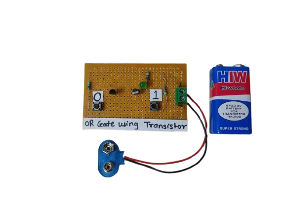
An OR gate using transistors is a basic logic circuit built using NPN transistors that performs the logical OR function. It gives a high output when at least one input is high. This is a fundamental building block in digital electronics and can be implemented using discrete components like transistors and resistors.
₹145.00
